 NOTE: Articles in this series were written in an order that might make "skipping around" confusing. If you didn't start at the beginning, you might want to CLICK HERE.
If you just finished reading my "Air in Fuel (pt 1)" article about THE HUTCH MOD, the next part will be a quick refresher. If not, it will set you up to understand why Air in Diesel Fuel is an important concern and why we look at different ways of preventing it.
SOME QUICK DEFINITIONS: before we go any further, I wanted to quickly cover the 2 types of air that get discussed when talking about diesel fuel systems.
- FREE AIR : free air is, for the purposes of these discussions, visible air bubbles in the fuel. Using a clear hose on the fuel system, free air can be easily seen by lighting up the hose with a flashlight, and may be in the form of obvious large bubbles or may look more like "flecks" floating in the fuel because the bubbles are so small (but still visible). It can also be seen floating at the top of the fuel tank as foam. This is the easiest air to deal with.
- ENTRAINED AIR : entrained air is air that is so "mixed into" the fuel that it is no longer visible. It is air that is essentially "in solution" with the fuel. Entrained air is much harder to remove.
So, why is air in the fuel actually problematic? In a nutshell the issue is three-fold: air is compressible, air does not make power and air does NOT work to lubricate or cushion moving metal parts.
The compressibility of air is problematic when you consider that some diesel fuel injectors/injection pumps have a piston with the sole job of forcing fuel through the injector nozzle on command from the computer or based on pump timing. When that piston starts to move, if there is air in the fuel cavity, some of the piston travel will be wasted compressing the air instead of moving the fuel through the nozzle, resulting in delayed injection timing, loss of performance, loss of economy, etc. This issue may be a little less critical in common rail systems where the fuel is constantly at injection pressure and the injector is simply an electronically controlled on/off valve.
Additionally, any space being taken up by air is space in the fuel system that should have been filled with fuel. Since diesels are throttled on the amount of fuel that is injected, that missing fuel that was replaced by air can result in unbalanced operation or an overall loss of power. How much depends on just how much air made it to the injector(s).
Lastly, there are internal parts of fuel injectors that are lubricated and/or cushioned by the presence of diesel fuel. If some of that fuel is replaced with air, the risk of moving parts colliding without cushion, or rubbing against each other without lubrication increases. Over time, this can result in premature wear or failure in the injectors.
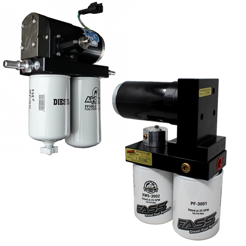
NOW ON TO THE FASS/AIRDOG DISCUSSION...
In my previous article, I discussed a proven method of PASSIVE AIR REMOVAL that we have used in 7.3L Ford Powerstrokes for over 20 years. I call it "Passive" because it isn't technically "Removal", it is really a method of "Prevention". This article will be discussing devices that I consider to be ACTIVE AIR REMOVAL, in that they involve the use of specific methods to actually remove air that has already made it into the fuel stream.
Much of my knowledge on the operation of these devices comes from many conversations with Charlie Ekstam (R.I.P.). Charlie was the founder of "Fuel Preporator, International" (hopefully I'm remembering the company name correctly, this was all a long time ago), and was the original patent holder for the technology used to remove air from diesel fuel. Fuel Preporator devices were originally developed for the OTR trucking industry, as well as diesel powered ships and trains, as a primary focus. Charlie later adapted the Fuel Preporator devices into a smaller format for the light duty diesel pickup market, and started building AirDog pumps. The original FP-100 and FP-150 AirDog part numbers are a nod to the parent business name, Fuel Preporator.
Brad Ekstam is the son of Charlie Ekstam, and the founder of FASS (Fuel Air Separation Systems). Without getting into any of the politics, rumors or drama (of which I know very little anyway), I offer this information simply to make the point that, at least at the beginning, both systems had their roots in the same technology and designs.
While the products by both companies are clearly not identical today, the basic way in which they remove air from diesel fuel remains similar enough that we can discuss them both in general terms and remain accurate.
SO HOW DO WE REMOVE AIR FROM DIESEL FUEL?
In the most basic of terms, these devices use three basic methods to remove air...VACUUM, FILTRATION and MULTIPLE FLOW PATHS. For the purposes of this discussion, I am going to leave out commentary about the removal of water or other contaminants/debris from the fuel, even though these devices perform that function as well.
In the first step of this process, Fuel/Air separating pump systems use VACUUM between the pump inlet and the pump itself (including the first filter) to "Grow" the air bubbles. Imagine placing a 4" diameter balloon into a sealed container that is larger than the balloon, then drawing a vacuum (reducing the atmospheric pressure around the balloon) in that sealed container. The internal pressure of the balloon will cause it to grow as the external pressure around the balloon drops, as described by Boyles Law (p1v1=p2v2). Much like the balloon, the air bubbles in the fuel start out small, but as they experience a vacuum in the pre-filter, the internal pressure in the bubbles causes them to grow in size. This size growth isn't really the goal though, because once the fuel passes through the pump, it will be on the pressure side of the system and the air bubbles will shrink again (likely smaller than it was initially, due to the now higher atmospheric pressure from the pump). The goal is for the larger bubbles of air on the suction side of the system to find other larger bubbles of air and merge with them (making the merged bubble even larger than the original unmerged bubbles), such that when they find themselves on the pressure side of the pump, they are larger than they would have otherwise been. The other goal is for the vacuum to pull as much of the entrained air as possible into bubbles that can potentially merge and grow, but at least remain in a bubble state that has a better chance of removal.
The next step in removing air from the fuel is FILTRATION. Filtration is a process where a material that needs to be cleaned is passed through a mesh of some sort (fuel filter in this case). Particles or debris that are larger than the holes in the mesh cannot pass through, and remain on one side, while the material that can pass through the mesh ends up on the other side. In the case of these fuel/air separating pump systems, the goal is to keep the air on one side of the filter while allowing the fuel for the engine to pass to the other side. As you can imagine, the size of the air bubbles (free air) in the fuel will play a role in whether they can pass through the mesh, which is why the vacuum step is so important.
So what happens to the air that is separated from the fuel and left on the outside of the filter element? This is where the MULTIPLE FLOW PATHS come into play, along with the STANDPIPE in the center of the fuel filter. A typical filter allows the fluid to pass through the filter, and whatever is captured by the filter media collects and remains (which is why you have to change it periodically), and whatever passes through the filter exits for use elsewhere in the system. In the case of the Fuel/Air separating pump systems, the outlet going to the engine comes from the inside of the fuel filter media (air removed), and is picked up by a standpipe that reaches down toward the bottom of the fuel filter canister. The air that is gathering on the outside of the fuel filter media has its own exit path, through a pressure regulator, that returns to the fuel tank. Once the pressure in the fuel filter is high enough to open the regulator, the path back to the fuel tank is opened and some fuel carrying the air that was removed by the vacuum and filtration processes is carried back to the tank. This is primarily "Free Air" that will (for the most part) rise to the top of the fuel tank and dissipate, though the process of being dumped into the fuel tank can cause some air to be re-entrained back into the fuel. The standpipe is important as well, because no filter is 100% efficient and some air will certainly make it through the filter media. When that happens, that air will rise to the top of the cavity inside the filter, where a small orifice bleeds off fuel into the return back to the fuel tank (same path as the outside of the filter). Having multiple paths for air to get to the fuel tank return line, and the standpipe picking up the "clean" fuel from the bottom of the filter cavity ensures that the absolute least amount of air can be picked up and sent to the engine.
Hopefully that gives you a better understanding of how these Fuel/Air separation pump systems work, and if you are debating purchasing one, helps you with your decision. I do have a few other thoughts below that I would lump more into the "Opinion" category, based on years of doing fuel system tech support and a bunch of time flowing these pumps on our fuel system flow bench. I suspect that both of the companies making these pump systems might disagree with me on some of these points, they are certainly entitled to do so, I simply include them for your consideration, so you can make the most informed decision possible.
OPINION #1 : Based entirely on the understanding of how these devices work (detailed above), I personally believe that todays use of "High Pressure" air removal pump systems (55+ psi) sacrifices air removal efficiency for cost and simplicity, compared to how we did it in the early days. When these devices were first released for the 7.3L and 6.0L platforms, they made a max of 10-15psi and acted as "Helper Pumps" that cleaned the fuel, removed the air and fed low pressure fuel to the inlet of the OEM pump. The OEM pump then stepped the fuel pressure up to the correct operating pressure (55-65psi in 7.3L/6.0L) and sent it along to the engine. Since the pump was making a max of 15psi in the filter canister, the air bubbles would have been larger (Boyles Law / p1v1=p2v2) and therefore easier to remove (as compared to todays 55-65psi). As the high performance market expanded and performance fuel injectors drove the need for higher volume pumps, these air removal pump systems moved to become "Replacement Pumps" instead of "Helper Pumps". As such, they now run at the OEM/Regulated Return pump pressures of 55-65psi and provide higher than OEM volume levels to support larger injectors and higher HP builds. All of this is a long way of saying that if maximum air removal is your highest priority, find a low pressure version of one of these pumps, let it scrub your fuel and remove the air, and plumb it to another pump to step the pressure up for the engine. This is how my personal truck is plumbed.
OPINION #2 : Due to the fact that these Fuel/Air separating pump systems have their own pressure regulator, some people want to make them the sole regulator in their 7.3L/6.0L fuel system as a way to save on cost. This may work OK in other applications where the fuel is going through another pump (CP3/4,etc), but I personally feel that it is a mistake in the HEUI applications. The built in regulator in these pumps is both too far away from the fuel rail and represents a potentially large point of pressure drop (see Opinion #3 below) in the fuel system just by itself. Couple that with every other possible point of pressure drop between the pump outlet and the fuel rail (sharp turns, restrictive fittings and the fuel injectors themselves) and you end up with a very good chance that the pressure in the rail does not match the outlet pressure of the pump. I believe that it will always be best to run a pump like this (with a built in regulator) at 10-15psi higher than the pressure desired in the fuel rail, and then regulate the actual rail pressure down using a bypass style fuel pressure regulator that is in the system AFTER every possible source of pressure drop. This will result in the fuel pressure in the fuel rails being as close as possible to desired at all times, provided the pump is moving the volume of fuel necessary.
OPINION #3 : In a future article, I will be discussing some of the results and information I gathered while working on our fuel system flow bench. Since this discussion is specifically about the commonly available Fuel/Air separating pump systems, I figured it might be useful to include some of that information here. On a typical fuel pump flow curve, as the fuel pressure increases, the flow rate (measured in Gallons Per Hour/GPH) flowing to the engine decreases in a pretty straight/linear manner. Seeing this while testing the different Fuel/Air separating pumps systems was not at all a surprise, I expected it. What did surprise me was just how aggressively the pump flow curves turned toward 0gph when the pumps regulator started opening (remember, these pumps have an internal regulator with a fuel return back to the fuel tank). The change was far from linear, and it caused me to spend a lot of extra time on the bench with these pumps in order to get a better understanding of how they behave. While the two different brands of these pumps handle their fuel pressure regulation differently, they end up with very similar results.
- One brand uses a basic relief valve type regulator, controlled by a spring and either a ball or poppet (depending on the version). When the fuel pressure is high enough to push the regulator off the seat (overcome the spring pressure), fuel passes through the port and out a large return line back to the tank. Any fuel being returned to the tank amounts to fuel that isn't being sent to the engine, thereby reducing the GPH of fuel available to the engine. Even using the higher rate regulator spring that is commonly available for this pump, the amount of return fuel and the loss of GPH to the engine were significant as soon as 20psi before the pressure rating of the regulator spring.
- The other brand just recently changed to a diaphragm style adjustable regulator on the pump. I tested both the older version and the new diaphragm version of this pump, and I can definitively say that the diaphragm version would be my preference. In either case, because this particular brand of pump only flows a small amount of fuel back to the tank when the regulator opens (enough to carry the air back), and internally recirculates the majority of the "pressure relief" fuel, it seemed to carry its linear flow rate out to a little closer to the regulator max before the flow curve turned toward 0gph. That said, I did find it interesting that I could literally tell when the internal regulator went fully open and the flow rate was going to tank by sound, it was very "on\off". The turn toward 0gph seemed to be more like 5-10psi before the regulator max on at least the diaphragm version of this pump, the older version was more like 10-15psi before max.
- In the case of either of these Fuel/Air separating pump systems, I used to recommend setting the pumps MAX pressure to 5-10psi MORE than what you wanted your engine pressure regulator set at. After seeing how they behave on the flow bench, I'm now recommending a split of more like 10-15psi (if possible) in order to make sure that the system isn't operating too close to the point where the flow turns aggressively toward 0gph. In the case of the pump with the spring/poppet style regulator, we have a kit that will configure that pump for the absolute best flow performance @ 75psi max at the pump and 65psi at the engine, based on testing on our flow bench. With our kit, this pump outflows the competitors adjustable diaphragm pump (set at 80psi max at the pump and 65psi at the engine) by a small margin.

Author: Dennis Schroeder - Co-Owner of Strictly Diesel
Dennis has been Designing, Building and Supporting Aftermarket Fuel Systems for 7.3L and 6.0L Powerstrokes since 2001.