
 94-97 "Old Body Style" 7.3L Powerstroke Fuel Pump Wiring Harness Diagnostics
From time to time we have customers that either need some help understanding how this harness works, or need some help figuring out why it isn't working correctly in their truck. This article will cover the complete operation of our OBS Fuel Pump Harness so that even those with limited automotive electrical understanding can locate and fix a problem if needed.
NOTE: If diagnosing electrical issues, we always recommend having a good DVOM (digital volt ohm meter) handy. A simple "test light" can help with some problems, but leaves a lot to be desired when trying to figure out some types of problems. Also, all descriptions of operation as well as diagnostic tests assume that the truck has good batteries, good battery cables, good chassis grounds, tight battery terminals, etc. Before attempting to diagnose ANY electrical issue, it's a good idea to make sure that you are not dealing with a simple low battery, loose cable or bad ground first.
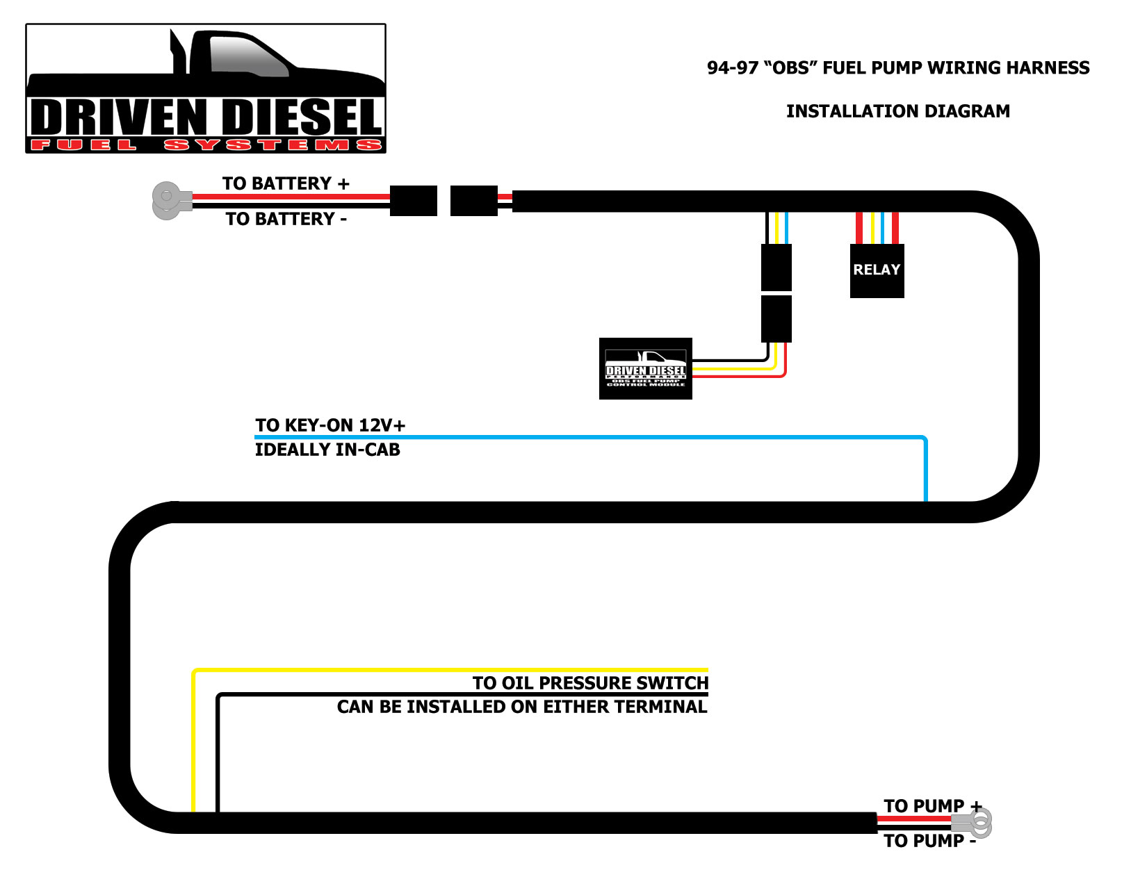
OBS PUMP HARNESS DIAGRAM:
HARNESS COMPONENT IDENTIFICATION AND DESCRIPTION:
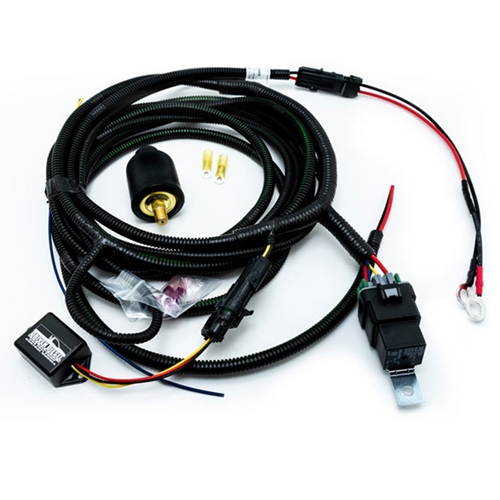
BATTERY PIGTAIL: This is shown at the top left in the above diagram. This pigtail consists of a 2-Wire Weatherpack connector with about 12" of wire that is terminated with large ring terminals. It is important to note that the Positive wire in this pigtail contains a 30A Fusible Link (not shown in diagram). PURPOSE: The battery pigtail makes the connection to the battery and provides fused protection for the harness.
PUMP CONTROLLER: The pump controller box has the Driven Diesel logo on it, with 3 wires and a 3-Wire Weatherpack connector. The pump controller plugs into the main harness near the relay. PURPOSE: The pump controller provides timed pump operation at key-on, causing the pump to stop running if the engine is not started within about 20 seconds.
PUMP RELAY: Shown as "Relay" on the diagram, this component is the box with the metal tab and 4 wires coming from the bottom. PURPOSE: The relay is the switch that turns the fuel pump on and off based on input from either the Pump Controller or the Oil Pressure Switch.
OIL PRESSURE SWITCH: This is not shown on the diagram, but connects to the Black and Yellow wires. PURPOSE: The oil pressure switch takes over for the Pump Controller and keeps the fuel pump running when the engine is running.
HARNESS WIRE COLORS AND FUNCTIONS:
RED: In the Battery Pigtail and the Main Harness leading to the Relay, the Red wire is connected to the (+) terminal of the battery and is always hot (unless the fusible link blows). After the Relay and all the way to the fuel pump, the Red wire is Switched 12v+ to run the fuel pump only when the relay is activated.
BLACK: Once the Battery Pigtail is connected to the (-) terminal of the battery, every black wire in the harness is connected to full time ground.
BLUE: The blue wire is a key switched 12v+ trigger for the Pump Controller, and the (+) trigger for the relay. Any time the key is ON, the blue wire should have full battery voltage.
YELLOW: The yellow wire is the (-) trigger for the relay. When connected to ground (via the Oil Pressure Switch or Pump Controller), the yellow wire causes the relay to switch and the fuel pump to run.
HARNESS OPERATION (Once Fully/Properly Installed):
At Key-On, the Blue Wire will get 12v+. This powers up the Pump Controller, which immediately connects the Yellow Wire to ground and starts a 20 second countdown timer. When the Yellow Wire is connected to ground at the same time the Blue Wire is connected to 12v+, the Relay activates and the pump starts running. If you do not start the truck, at the end of 20 seconds, the Pump Controller disconnects the Yellow Wire from ground which causes the Relay to deactivate and the pump stops running. If you do start the truck, the Oil Pressure Switch will close and connect the Yellow Wire to ground. Even though the Pump Controller will time out at 20 seconds, the Yellow wire will remain connected to ground for as long as the engine is running and the Oil Pressure Switch is seeing 4psi of oil pressure.
When you turn off the key to shut off the truck, the Blue Wire loses 12v+ from the ignition switch being turned off. When the engine stops running, the Oil Pressure Switch opens and disconnects the Yellow Wire from ground. Either of these is enough to cause the Relay to deactivate and the pump to stop running.
COMMON TROUBLESHOOTING SCENARIOS:
TIP: Disconnecting the yellow and black wires from the Oil Pressure Switch and connecting them to each other bypasses BOTH the Oil Pressure Switch and the Pump Controller. If you do this and your fuel pump suddenly starts running with the key on, one of the next 2 scenarios applies.
PUMP RUNS FOR 20 SECONDS AND STOPS, EVEN IF ENGINE STARTED: If the pump runs at Key-On and stops after 20 seconds, this tells us that the connection at the battery is good, the fusible link is good, the pump controller is good and the blue wire is getting 12v+ as it should. The first thing to look at is the Oil Pressure Switch. If one or both wires is not securely connected to the switch, replace connectors and reattach and test again. If the wires are still connected securely, the switch has probably failed. Disconnect the yellow and black wires from the oil pressure switch. Turn the key on and let the pump controller time out so the pump stops running. Jumper the yellow and black wires to each other (you can use a paper clip or similar for the test). If the pump runs any time you connect the yellow and black wires together (with the key on), you need a new oil pressure switch. To make the truck drivable while you wait for a new pressure switch, simply make a more permanent jumper from a short piece of wire and some correct terminals. The pump will run 100% of the time when the KEY IS ON, but you will have a drivable truck until you put a new switch in. CLICK HERE to order a replacement Oil Pressure Switch.
PUMP DOES NOT RUN DURING "WAIT TO START" BUT DOES RUN IF ENGINE STARTED: If the pump runs with the engine started, this tells us that the connection at the battery is good, the fusible link is good, the oil pressure switch is good and the blue wire is getting 12v+. What is not operating is the Pump Controller. Uplug the pump controller at the 3-wire weatherpack connector and use a DVOM (set for DC Volts) to check the voltage at the blue wire (harness side plug). The blue wire at the connector should show battery voltage with the key on. Next, using the DVOM in continuity mode (tone), check for continuity between the black wire (harness side plug) and the (-) terminal of the battery, you should get a tone (or show a very low ohm reading) all the time, even with the key off. Assuming that the blue wire has 12v+ and the black wire has continuity to ground, plug the Pump Controller back in to the harness and cycle the key again. If the pump still doesn't run during the "wait to start" cycle, the controller has failed and needs to be replaced. Contact Strictly Diesel at 623-582-4404 for replacement information.
MORE ADVANCED TROUBLESHOOTING:
PUMP NEVER RUNS AT ALL: This is the situation where all of the information above will become useful. The following is how I would diagnose this. Some of these steps will require a second person to help by turning the key on and off while you watch a DVOM, etc.
Step 1: Check all harness connections (at the battery, pump, pressure switch, pump controller and blue wire) and make sure they are secure, connected and that no connector pins have pushed out. Repair any issues found and re-test.
Step 2: Using a DVOM set for DC Volts, check the voltage at the pump (+) and (-) terminals WITH THE PUMP CONNECTED and the key on. If you have battery voltage (12v approx) at the pump, but the pump is not running, you more than likely have a fuel pump problem, not a harness problem. If you have significantly less than battery voltage at the pump, you will need to look at the harness more. The next steps assume little to no voltage at the pump.
Step 3: Check for Relay Operation. Hold on to the Relay while another person turns the key on and off. You should be able to feel the relay "click" on and off as they cycle the key. Keep in mind that this is NOT a guarantee of relay functionality, just a guide for where to move next.
RELAY NOT CLICKING: either the blue wire does not have battery voltage at key-on, the black wire is not connected to ground, the pump controller is not functioning or the relay has failed.
RELAY IS CLICKING: either the red wire is not connected to 12v+, fusible link is blown, the relay pins are not making good contact in the socket or the relay has failed.
From here we get down to the basics. Do we have connectivity and voltage where expected. A Digital Volt Ohm Meter (DVOM) will be needed, and this article assumes you have a basic idea of how to use one.
Step 4: Disconnect the Battery Pigtail from the Main Harness at the 2-Wire weatherpack connector. Using a DVOM (set for DC Volts), check the voltage on the PIGTAIL pin for the Red wire. If you do not have the same voltage in the connector on the Red wire that you do right at the battery (12" of wire away), the Fusible link needs to be replaced. We have not had to replace these often, but it is possible. Contact Strictly Diesel at 623-582-4404 for replacement information. The next steps assume that you have the same voltage at the 2-wire connector as you do at the battery. RECONNECT THE PIGTAIL TO THE HARNESS! Make sure none of the pins push out!
Step 5: Push the release tab on the relay and separate the Relay (top) from the Socket (bottom). Visually inspect the relay socket and relay pins for signs of arcing (burn spots). If the relay and socket are clean and appear normal, proceed to the next step. If they do not appear normal, take some pictures of what you found and send them in to us at sales@strictlydiesel.com. Follow up by contacting Strictly Diesel at 623-582-4404 to discuss repair options.
Step 6: The tests in the next 2 steps will use the exposed terminals where the relay plugs in. Using the DVOM (set for DC Volts), check the voltage on the red wire that goes to the battery, it should be the same as battery voltage. Note: there are 2 red wires, one will have battery voltage and the other will show 0v, this is normal. Next, put the test lead on the exposed terminal for the blue wire. It should read 0v with the key off, and battery voltage with the key on. If you do not have battery voltage on the red wire to the battery (full time) and the blue wire (key on), you need to investigate these wires and their connections.
Step 7: NOTE: "Key On" tests in this step need to be made within 10-15 seconds of turning the key on, before the Pump Controller deactivates. If you wait too long, you will need to turn the key off and back on again. Now, switch your DVOM to continuity (tone) mode and check the connection between the battery (-) terminal and the yellow wire lead at the socket. You should have tone and/or a very low ohm reading with the key on, and no tone with the key off. If the yellow wire doesn't have continuity to the battery with the key on, the Pump Controller may not be functioning. Disconnect the yellow and black wires from the oil pressure switch, jumper them together temporarily and repeat this step again. If you now have continuity to ground, the Pump Controller has failed. If you still do not have continuity to ground, the black wire needs to be checked at the battery because the harness has no ground.
Step 8: With the relay still removed from the socket, use (2) short pieces of wire to connect relay pin 85 to the (+) battery terminal and relay pin 86 to the (-) battery terminal. This will cause the relay to activate, and each time you make or break the connection, the relay should "click". If you want to take this test a bit further, you can put the test leads of your DVOM (set for continuity/tone) on relay terminals 87 and 30. Any time you make contact to the battery and the relay clicks closed, you should have tone. The tone should stop when you break the connection with the battery. If all of the checks in this step are good, plug the relay back into the socket and make sure it snaps fully into place.
By now, you should have identified the problem in your harness.

Author: Dennis Schroeder - Co-Owner of Strictly Diesel
Dennis has been Designing, Building and Supporting Aftermarket Fuel Systems for 7.3L and 6.0L Powerstrokes since 2001.